Navigation
ATLAS Reveals Hidden Wellbore Restrictions Before ESP Deployment
APPLICATION
/ ESP placement
/ MicroDLS/tortuosity analysis
/ Effective Free ID modeling
/ Bending moment and radial displacement modeling
TECHNOLOGY
/ Advanced Trajectory & Lift Analysis Service (ATLAS)
/ Keeper Gyro
LOCATION
Onshore, Columbia
DOWNLOAD CASE HISTORY
/ PDF File
CHALLENGE
An operator needed to evaluate whether a planned ESP/motor assembly could be deployed and set at depth without being Exposed to excessive bending or restriction risk. Standard survey spacing could not clearly identify localized micro-doglegs, tortuosity, or effective Free ID restrictions that could create bending loads on the ESP, motor, cable, and associated completion components.
The operator also needed to compare two possible assembly configurations: one without a Y-tool/by-pass tubing configuration and one with a Y-tool/by-pass tubing configuration.
SOLUTION
Scientific Drilling acquired high-resolution cased hole gyro survey data and applied its Advanced Trajectory & Lift Analysis Service (ATLAS) to model the actual wellpath at 1 ft increments.
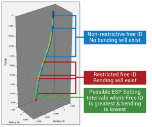
The analysis evaluated localized MicroDLS/tortuosity, calculated Effective Free ID for multiple assembly lengths, and compared two ESP deployment scenarios. The first scenario modeled an ESP + intake/seal + motor assembly with a 95.08 ft length, 4.00 in ESP OD, and 5.62 in motor OD. The second scenario evaluated the added Y-tool/by-pass tubing configuration with larger pass-through requirements. ATLAS converted the high-density survey into clear setting-depth intelligence, including Free ID restriction intervals, 3D visualization, and modeled bending moment/displacement at the planned setting interval.
rESULTS
ATLAS gave the operator a clearer decision basis before running the ESP. For Scenario 1, the analysis identified an optimum setting interval between 8,017 ft and 8,250 ft MD where Free ID was greatest and bending was not expected for the modeled ESP OD. For Scenario 2, the larger Y-tool/by-pass tubing configuration had no lower 9 5/8 in casing interval where the assembly could be set without bending, but ATLAS identified 8,144 ft to 8,250 ft MD as the lowest bending interval. The analysis also modeled a proposed set between 8,118 ft and 8,240 ft MD, showing a maximum bending moment force of 294 lbf at 66 ft from the top of the BHA and maximum radial displacement of 0.17 in at approximately 44 ft from the top. This allowed the operator to compare configuration risk, adjust deployment strategy, evaluate running speed, and make a more informed setting depth decision before exposing the equipment to downhole risk.
YOU MAY ALSO BE INTERESTED IN
Ellipse of Uncertainty Reduction with Dual North Survey Combination Service